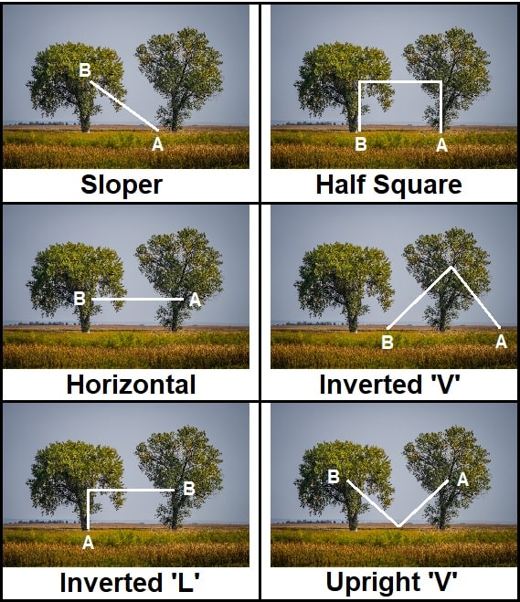
The 60-foot end-fed HF JPole Sr Antenna and also the 34-foot end-fed HF JPole Jr Antenna can be deployed in at least six different ways (see image). Whether you are using the Sr or the Jr version, you may use a tuner to achieve a near perfect SWR on these bands.
End-Fed Antenna Configurations
Sloper Configuration Deployment as a Sloper configuration will DX into the greyline on 7.0-19MHz in either the morning or evening and evening NVIS propagation on 7.0MHz and lower frequencies, which will both occur in the direction of the slope. Proper deployment places the antenna at an angle that achieves a launch in the desired take off angle to the horizon.
Half Square Configuration Deployment as a Half Square configuration will provide evening NVIS coverage on 7.0MHz and lower frequencies, daytime NVIS coverage from 14MHz and higher frequencies, and DX from 7.0-19MHz during evening or daytime deployments. Proper deployment places 50% of the length of the antenna across the top and 25% on both legs, where the top is at a height equal the deployed length of each leg.
Horizontal Configuration Deployment in a Horizontal configuration will provide evening NVIS coverage on 7.0MHz and lower frequencies, daytime NVIS coverage from 14MHz and higher frequencies, and DX from 7.0-19MHz during evening or daytime deployments. Proper deployment to enhance NVIS places the element lower and with the horizontal configuration, which is parallel to the earth. In practice, to optimize NVIS (Near Vertical Incident Skywave) performance, deploy the antenna horizontally at a height of 1/8 wavelength on any given band for a 0–650 km (0–400 miles) coverage area. Where DX will occur into the greyline from 7.0-19MHz during evening or daytime deployments.
Inverted “V” Configuration Deployment as an Inverted “V” configuration will provide evening NVIS propagation on 7.0MHz and lower frequencies, daytime NVIS coverage from 14MHz and higher frequencies, and DX into the greyline from 7.0-19MHz during evening or daytime deployments. Proper deployment places 50% of either side of the element on each leg of the V, where there is no less than 120 degrees of separation between the two elements.
Inverted “L” Configuration Deployment as an Inverted “L” configuration will provide evening NVIS on 7.0MHz and lower frequencies, daytime NVIS coverage from 14MHz and higher frequencies. Proper deployment uses places 1/3 of the element vertically and 2/3 of the element horizontally at the top.
Upright “V” Configuration Deployment as an End-Fed Inverted “V” configuration will provide evening NVIS propagation on 7.0MHz and lower frequencies, NVIS on 7.0-19MHz during evening or daytime deployments, and DX into the greyline from 7.0-19MHz during evening or daytime deployments. Proper deployment places 50% of either side of the element on each leg of the V, where there is no less than 120 degrees of separation between the two elements.
What not to do
We do not recommend installing this antenna as a Vertical in high noise environments. As verticals are inherently prone to high noise (RFI).
Q&A
Why are there two separate wires that run parallel for these two antennas?
- The shorter wire increases the amount of capacitance and is basically like a tuning stub. Whereby, the added capacitance is similar to an air capacitor having two plates. In the case of the two wires, they are separated with equidistance by the ZIP Cord.
Is a ground or counterpoise/radial important for these antennas?
- These are End fed antenna. So, you do not need to ground it. Grounding your equipment per manufacturer specifications is what everything (the antenna system, coax system, and your equipment) relies on.