Introduction
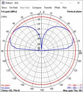
High Frequency (HF) antennas are crucial for long-distance (DX) and Near Vertical Incidence Skywave (NVIS) communications. This guidance outlines the best practices for deploying your Alpha HF Antenna to achieve optimal performance for both DX and/or NVIS operations.
Understanding DX and NVIS
- DX (Long-Distance Communication): DX communication is a favorite of amateur ham radio operators, and it relies on low-angle radiation to reach distant locations by reflecting off the ionosphere.
- NVIS (Near Vertical Incidence Skywave): NVIS communication is a favorite of military and EMCOMM operators, and it uses high-angle radiation to cover short to medium distances by reflecting signals almost vertically off the ionosphere.
- Now you can have both DX and NVIS by using the Alpha EmComm line of antennas.
Antenna Configurations (Depicted Below)
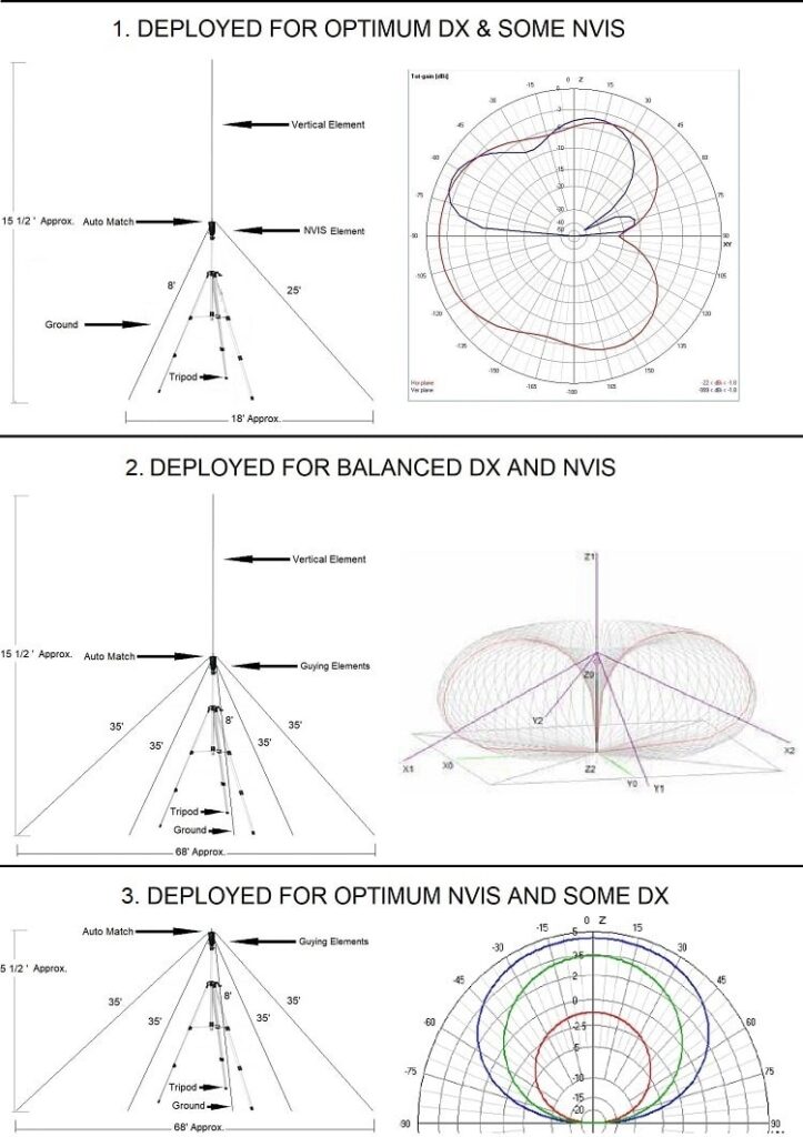
- Optimum DX and some NVIS (Directional) for 6-80M
- Configuration: Deploy the Auto Match at approximately 5 1/2 feet and install the Vertical & one 25′ NVIS Element on the top of the auto match and one 8′ Ground wire towards the bottom of the auto match so that they are deployed in opposite directions at 180 degrees from each other to achieve the signal pattern shown in Figure 1.
- Balanced DX and NVIS (Omnidirectional) for 10-160M
- Configuration a: Deploy the Auto Match at approximately 5 1/2 feet and install the Vertical & four 35′ NVIS Elements on the top of the auto match and one 8′ Ground wire towards the bottom of the auto match so that the NVIS Elements are deployed at 45-degree angles from each other to achieve the signal pattern shown in Figure 2.
- Configuration b: To enhance omnidirectional DX with some NVIS, move the four NVIS Elements from the top of the auto match on the bolt that is towards the bottom of the auto match.
- Optimum DX and some NVIS (Omnidirectional) for 10-160M
- Configuration: Deploy the Auto Match at approximately 5 1/2 feet and attach the four 35′ NVIS Elements on the top of the auto match and one 8′ Ground wire towards the bottom of the auto match so that the NVIS Elements are deployed at 45-degree angles from each other to achieve the signal pattern shown in Figure 3.
Deployment Best Practices
- Site Selection:
- Choose a location with minimal obstructions for DX antennas to ensure a clear path to the horizon.
- For NVIS antennas, ensure the site allows adequate space for the antenna elements to be fully deployed at the correct angles for high-angle radiation.
- Grounding element:
- All deployments rely on a static drain called the ground wire/element, which enables the system to have a complete circuit to ground. This both lowers the receive noise floor and provides a path to ground for common mode current.
- Tuning and Matching:
- Use an antenna tuner to ensure the antenna appears resonant at the desired operating frequencies to your equipment.
Conclusion
Deploying HF antennas for optimum DX and NVIS performance requires careful consideration of site selection and deployment configuration (1, 2 a or b, or 3). By following these best practices, you can achieve reliable and effective communication over both long and short distances.
Feel free to ask if you need more details on any specific aspect of HF antenna deployment.


