10-160M HF EmComm end fed JPole Sr

$219.00

10-160M

Tune Free HF End Fed Antenna

Availability: 16 in stock

Options
RG58u Coax
1 × 50 feet of RG-58/U Coax w/PL-259s
$49.00
RG58u Coax
1 × 18 feet of RG-58/U Coax w/PL-259s
$34.00

60-foot HF end fed antenna for 10-160 meters that enables a tuner to achieve a near perfect SWR, with limited efficiency while using a tuner on 160 meters. Rated #1 by eHam users as the best horizontal end-fed antenna for base operations for over 10 years.

We listen!

Suggest a price without Options and marketing will review your expectations.

HF End Fed Antenna Specifications

  • Frequency Coverage: 1.8-29.7 MHz (160-10 Meters)
  • Peak Power: 250 PEP SSB, 125 CW, or 25 watts for digital modes. NOTE – The MIL-STD-188 M110a digital communications mode is rated at bursts of 100 watts digital for up to 1 minute using the MIL-STD Data Modem Terminal (MS-DMT) and Automated Message Terminal (AMT) software applications.
  • Length: 60 Feet
  • Weight: 1 pound
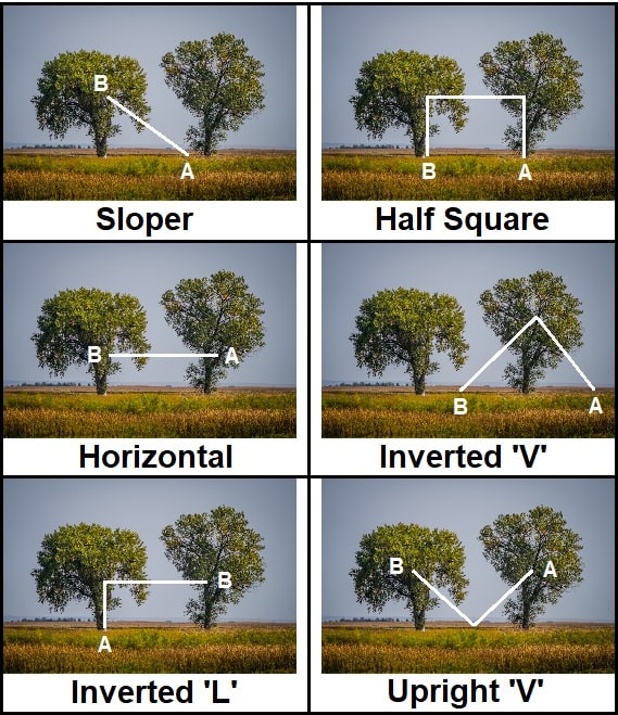
  • Configuration: End fed antenna configurable as Sloped or Horizontal
  • Connector: UHF type SO-239

Analysis

60 Foot element
Band SWR
10 Meters 1.61
12 Meters 2.43
15 Meters 1.75
17 Meters 1.52
20 Meters 2.20
40 Meters 2.67
80 Meters 2.08

HF JPole Sr antenna SWR Analysis

HF End Fed Antenna Deployment 

Run the end fed antenna as a sloped system for good NVIS and DX results, or a flat top for good NVIS results. We test the antennas at 6 feet, however higher placement will enhance DX results while lower placement will enhance NVIS.


Click Image for the Configurations Page

end fed antenna deployment examples

We listen!

Suggest a price for this end fed antenna only without Options and marketing will review your expectations.

Specifications, prices, and descriptions are subject to change without notice.

Reviews

5.0
Based on 70 reviews
5 star
100
100%
4 star
0%
3 star
0%
2 star
0%
1 star
0%
1-5 of 70 reviews
  1. SB
  2. RH

    Unique design with the counterpoise routed along the radiating wire. I rarely use the antenna tuner my yt-991a has, good > 2.0 match almost across the spectrum with some deviation on 40 meters (2.5 SWR)

  3. DH

    Outstanding antenna. It exceeded my expectation especially since I have the feedpoint at a less than ideal height. I am very pleased with it.

  4. TC

    Needed a stealth setup so as not to upset my better half. Saw a great review on YouTube by HamJazz and he was spot on!
    Finally got the antenna installed today and it meets my expectations. Installed on top of a 6 foot wood fence. Made contacts on East Coast right off the bat from central Illinois. Tried to work California but there was to much QRM. Have not doubt I will cover all of North America and possibly beyond. Thanks Alpha.

  5. W
Weight 5 lbs
Dimensions 12 × 10 × 5 in
availability

Brand

Color

condition

Manufacturer

mpn

product type

, , , , , ,

aggregateRating

review

SKU

VHF UHF HF Antenna type

, , , ,

Q & A

Ask a question
Does this antenna need a support rope? Paul R. asked on April 18, 2024

Yes. Please see the manual for rope use here https://www.alphaantenna.com/manuals/JPole_Sr_v2.9_by_Alpha_Antenna.pdf

admin answered on April 24, 2024 store manager
(0) (0)
Add an answer
Should a BalUn or air choke be installed? Q A asked on December 28, 2023

You may need one mainly if you are experiencing common mode current, especially after you have placed ferrite beads on the devices power cord that is experiencing common mode current. Note - Sometimes resolution is made by simply moving the devices power cord to a different circuit. If, for example, you still hear your own transmission coming from a pair of speakers then we recommend reading the following article: "The Need (or not) for Antenna Baluns or Chokes": https://www.alphaantenna.com/community/hints-and-kinks/news/the-need-for-antenna-baluns-ensuring-efficient-signal-transmission/

admin answered on December 28, 2023 store manager
(0) (0)
Add an answer
How high should this antenna be installed? Q A asked on December 28, 2023

To enhance NVIS, mount the element lower than 8 feet in a horizontal configuration. For better DX, mount the element in the clear and sloped into the direction you want to launch your signal. For example, with one end at 6 feet and the other at 30 feet (Note that higher typically results in more DX). Again, the slope helps determine the angle and direction that your signal is launched.

admin answered on December 28, 2023 store manager
(0) (0)
Add an answer
How did you build this antenna to achieve such low SWR’s? Q A asked on December 14, 2023

Previous design: In July 2023 Alpha Antenna changed what was their 5:1 UnUn with a single element as the radiator and one element as the counterpoise.

Current design: The result of this change is an end fed fan dipole arrangement fed to a modified 5 to 1 UnUn.

What changed?: While monitoring with both RigExert and AIM analyzers, physical changes were made in real-time to the inductor with the new configuration of the two wire elements attached. Those analyzers simultaneously monitored all of the bands, while physical changes were made to the inductor. We stopped making changes once the best values were presented. During this process, we found that the shorter leg of the two wire elements also had to be modified to present excellent results. The value of the new UnUn has not been tested, nor do we care to test it, we simply enjoy the results of a finely tuned system.

Comments: To construct the UNUN, specialized tools were built on our 3-D printers. Without these tools, construction of the new UnUn in a production environment was nearly impossible. Fortunately, we use Fusion 360, which made designing the tools possible.

admin answered on December 14, 2023 store manager
(0) (0)
Add an answer
Regarding the 2 parallel elements that for the shape of a ‘J’; Is the 2nd wire a transmitting element like a dipole or is the 2nd element a counterpoise, and are both wires strung along the same axis or is the 2nd one sloped down beneath the 1st one at a steeper angle? Q A asked on December 8, 2023

The JPole (Jr & Sr) are derived from a fan dipole’s design, which simply enables RF to select the element(s) with the path of least resistance for the resonance required to provide acceptable SWRs. The second shorter element is an active element that that is attached to the longer element in a zip cord configuration. This enables the end fed JPole antenna to have access to 3 electrical lengths of wire. These lengths are: 1) The shortest element, 2) the longest element, 3) and an even longer combined length of 1 and 2. Then an inductor matches the impedance at the point where your 50-ohm coax attaches to the match. Operationally, the JPole Sr is designed with the optimum lengths of elements, and the 34-foot JPole Jr was designed for those who do not have the room to deploy a 60-foot JPole Sr antenna.

admin answered on December 8, 2023 store manager
(0) (0)
Add an answer
×


Scroll to Top
×